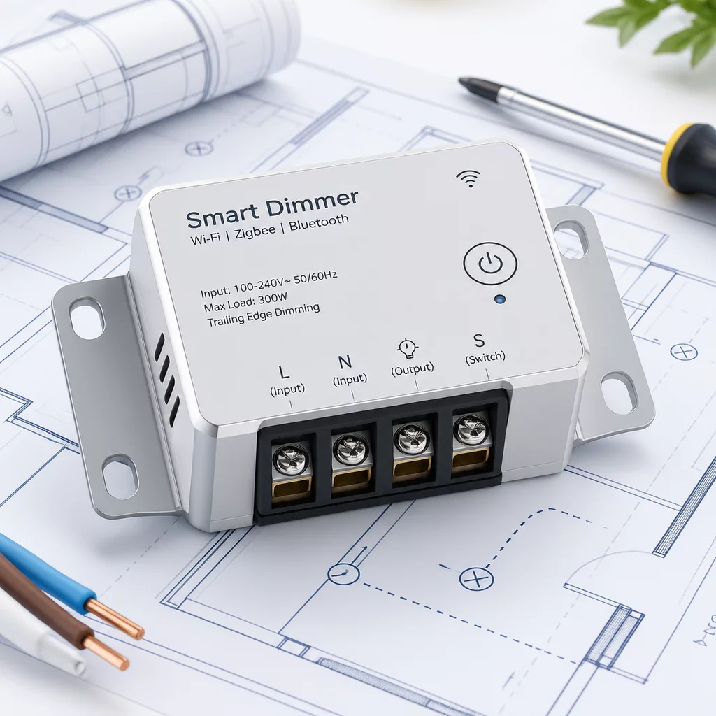
Shelly Dimmer 0-10V PM Gen4
Professional micro-module engineered for 0-10V ballast dimming, zero-loss electrical tracking, and autonomous local control.
Module for precise light regulation with built-in energy metering. It connects directly with standard 0-10V dimmable drivers, electronic ballasts, and variable speed motors, delivering ultra-smooth analog voltage modulation and active watt-hour telemetry without requiring third-party cloud connections.
Hardware Specifications
| Communication Protocols | Wi-Fi 802.11 b/g/n (2.4 GHz), Bluetooth Low Energy 4.2, Local WebSockets, MQTT, REST API |
| Operational Voltage | 110-240V AC ±10%, 50/60Hz (with low-voltage 0-10V DC control output loop) |
| Max Continuous Load | Up to 0.35A internal relay load / 100mA current sinking capacity on 0-10V circuit |
| Enclosure Material | UL94 V-0 Grade Flame-Retardant Polymer Housing |
| Operating Temperature | -20°C to +40°C (-4°F to 104°F) / Relative Humidity 30% to 70% non-condensing |
System Topology & Architecture
The Shelly Dimmer 0-10V PM Gen4 module integrates an isolated low-voltage digital-to-analog output converter with a high-accuracy current transformer for continuous telemetry. All schedules, micro-scripts, and threshold safeguards run straight on the 8MB onboard microchip. In the event of Wi-Fi outages, preset luminance levels and switch triggers stay fully functional.
Mesh Relay Node
Acts as an active protocol repeating station extending localized IoT range across domestic switchboards.
Zero-Crossing Sync
Prevents inrush voltage arcs on capacitive driver circuits during high-frequency switching operations.
Local Key Storage
Stores network security tokens on hardware-isolated non-volatile microchips for offline safety.
Installation Guidelines
Mount the micro-module directly into standard European or North American wall backboxes, inside false ceiling junction containers, or onto standard DIN rail adapters. Ensure that the 0-10V control leads are wired with correct polarity to avoid inverted brightness scaling.
- 01Isolate line breaker upstream prior to touching any backplate electrical terminals.
- 02Connect neutral and phase wiring following standard 1.5mm² solid-core copper recommendations.
- 03Push configuration button once to broadcast commissioning beacon over localized radio mesh.
Request Hardware Dispatch
Submit project requirements to arrange direct hardware allocation and deployment specifications.
Related Hardware Modules